 |
| Project Demo With OTA Updates |

This post is sponsored by PCBWay, with more than a decade in the field of PCB prototype and fabrication, PCBWay is committed to meeting the needs of their customers from different industries in terms of quality, delivery, cost-effectiveness and any other demanding requests.
As one of the most experienced PCB manufacturers in the World, PCBWay prides itself on being your best business partner as well as a good friend in every aspect of your PCB needs.
Pre-Requisites
Before you start, make sure you have the following:
- ESP32 Development Board: A popular and powerful microcontroller board for IoT projects.
- ESP-IDF Installed: Set up the ESP-IDF development framework on your computer. You can find installation instructions in the ESP-IDF documentation.
- DHT11 Sensor: A sensor that measures temperature and humidity.
We should also have an idea of what we are going to develop, and this is illustrated with the help of a Use Case Diagram as shown below.
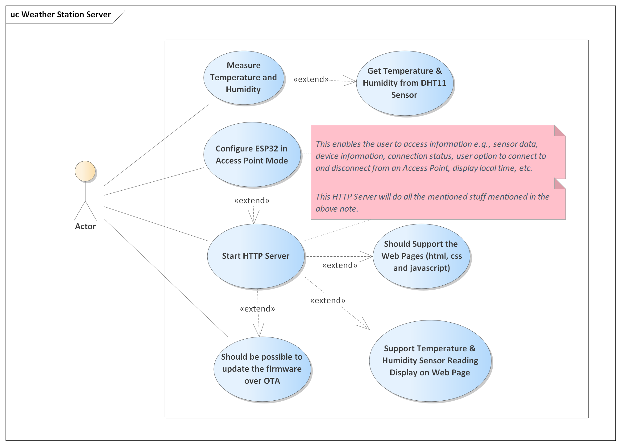 |
| Use Case Diagram Weather Station Web Server |
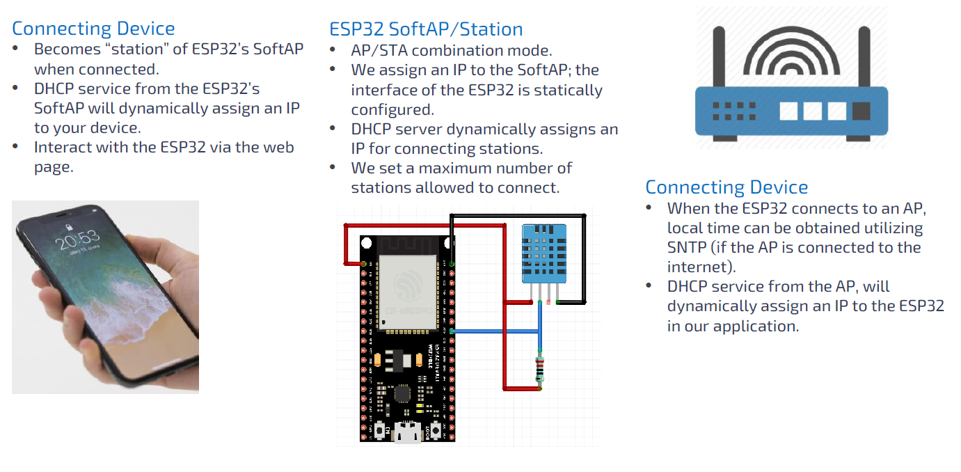
Step 1: Setting up the Hardware
- Connect the DHT11 sensor to the ESP32 board. Connect the VCC pin to 3.3V, GND to ground, and DATA to a GPIO pin of your choice (e.g., GPIO19).
Step 2: Creating the Project
This is a very basic topic and I am not going to cover that, you can use Eclipse-based ESP-IDF IDE or VS Code or even the command line version.
Step 3: Writing the Code
The project is divided into several modules and each module handles the individual tasks.
The first module is the "DHT11" sensor module, this module is used to get the temperature and humidity values from the "DHT11" sensor module. The source code for this module can be downloaded from the links given at the bottom of this page, but a brief overview is given here.
/* Private Variables */
static gpio_num_t dht_gpio;
static int64_t last_read_time = -2000000;
static dht11_reading_t last_read;
/* Private Function Prototypes */
static int dht11_wait_or_timeout(uint16_t useconds, int level);
static dht11_status_e dht11_check_checksum(uint8_t data[]);
static void dht11_send_start_signal( void );
static int dht11_check_response( void );
static dht11_reading_t dht11_timeout_error( void );
static dht11_reading_t dht11_crc_error( void );
/* Public Function Definitions */
void dht11_init(gpio_num_t gpio_num)
{
/* Wait for some seconds to make the device pass its initial unstable status */
vTaskDelay(DHT11_INITIAL_WAKEUP_DELAY / portTICK_PERIOD_MS);
dht_gpio = gpio_num;
}
dht11_reading_t dht11_read( void )
{
/* DHT11 sensor can take up-to 2 seconds for updated values, hence if some one
* call this function too early, then we should return the old value
* */
if( (esp_timer_get_time() - DHT11_READING_WAIT_DELAY) < last_read_time)
{
return last_read;
}
last_read_time = esp_timer_get_time();
uint8_t data[5] = {0,0,0,0,0};
/* trigger the start signal */
dht11_send_start_signal();
/* Check for DHT11 Host Signal, here DHT11 should pull the line low for 80us
* and then pull the line high for 80 us
*/
if( dht11_check_response() == DHT11_TIMEOUT_ERROR )
{
return last_read = dht11_timeout_error();
}
/* Now DHT11 will send 40 bits of data, each bit transmission begins with the
* low-voltage level that last around 50us, the following high-voltage level
* signal length decides whether the bit is "1" or "0"
*/
for(int i = 0; i < 40; i++)
{
/* Initial low signal, should be around 50 us, if more than that it is a
timeout error. */
if(dht11_wait_or_timeout(50, 0) == DHT11_TIMEOUT_ERROR)
{
return last_read = dht11_timeout_error();
}
/* Now the high signal length will determine whether it is a bit 1 or 0, here
we check maximum for 70 us second, but if pin gets low and the micro ticks
are greater than 28 us seconds, then it means bit is 1 else bit is 0 */
if(dht11_wait_or_timeout(70, 1) > 28)
{
/* Bit received is a 1 */
data[i/8] |= (1 << (7-(i%8)));
}
}
/* last step is to validate the received data by checking the checksum */
if(dht11_check_checksum(data) != DHT11_CHECKSUM_ERROR)
{
last_read.status = DHT11_OK;
last_read.temperature = data[2];
last_read.humidity = data[0];
}
else
{
last_read = dht11_crc_error();
}
return last_read;
}
/* Private Function Definitions */
static int dht11_wait_or_timeout(uint16_t useconds, int level)
{
int micros_ticks = 0;
while(gpio_get_level(dht_gpio) == level)
{
if(micros_ticks++ > useconds)
{
return DHT11_TIMEOUT_ERROR;
}
ets_delay_us(1);
}
return micros_ticks;
}
static dht11_status_e dht11_check_checksum( uint8_t data[] )
{
dht11_status_e dht_status = DHT11_CHECKSUM_ERROR;
if(data[4] == (data[0] + data[1] + data[2] + data[3]))
{
dht_status = DHT11_OK;
}
return dht_status;
}
static void dht11_send_start_signal( void )
{
/* Request Stage:
* To make the DHT11 send the sensor readings we have to send a request.
* The Request is to pull down the bus for more than 18ms, in order to give
* DHT11 time to understand it and then pull it up for 40 micro-seconds
*/
gpio_set_direction(dht_gpio, GPIO_MODE_OUTPUT);
gpio_set_level(dht_gpio, 0);
ets_delay_us(DHT11_START_SIGNAL_PULL_DOWN_DELAY); // 20ms delay
gpio_set_level(dht_gpio, 1);
ets_delay_us(DHT11_START_SIGNAL_PULL_UP_DELAY); // 40us delay
gpio_set_direction(dht_gpio, GPIO_MODE_INPUT);
}
static int dht11_check_response( void )
{
/* Wait for next step ~80us*/
if(dht11_wait_or_timeout(80, 0) == DHT11_TIMEOUT_ERROR)
return DHT11_TIMEOUT_ERROR;
/* Wait for next step ~80us*/
if(dht11_wait_or_timeout(80, 1) == DHT11_TIMEOUT_ERROR)
return DHT11_TIMEOUT_ERROR;
return DHT11_OK;
}
static dht11_reading_t dht11_timeout_error()
{
dht11_reading_t timeout_error = { DHT11_TIMEOUT_ERROR, -1, -1 };
return timeout_error;
}
static dht11_reading_t dht11_crc_error()
{
dht11_reading_t crc_error = { DHT11_CHECKSUM_ERROR, -1, -1 };
return crc_error;
}
This module takes the help of the timing details provided by the esp timer module to generate exact timing signals needed by the DHT11 sensor module.
The next module is the main module, we can also call this module as main task module, this is the starting point of the project and this module will initialize the DHT11 sensor module and also the WiFi Application module (which in turn will start the ESP32 in WiFi Access Point Mode).
void app_main(void)
{
dht11_reading_t dht11_value;
// Initialize NVS
esp_err_t ret = nvs_flash_init();
if (ret == ESP_ERR_NVS_NO_FREE_PAGES || ret == ESP_ERR_NVS_NEW_VERSION_FOUND)
{
ESP_ERROR_CHECK(nvs_flash_erase());
ret = nvs_flash_init();
}
ESP_ERROR_CHECK(ret);
// initialize led manager module
led_init();
// initialize the dht11 module
dht11_init(DHT11_GPIO_NUM);
// Start WiFi
wifi_app_start();
while (true)
{
// read the data from dht11 sensor
dht11_value = dht11_read();
// If reading is valid then only print
if( dht11_value.status == DHT11_OK )
{
temperature = (uint8_t)dht11_value.temperature;
humidity = (uint8_t)dht11_value.humidity;
ESP_LOGI(TAG, "Temperature: %d, Humidity: %d", temperature, humidity);
}
vTaskDelay(MAIN_TASK_PERIOD / portTICK_PERIOD_MS);
}
}
This module also measures the temperature and humidity values from the DHT11 sensor and stores them in module-specific global variables, which can be used to display the temperature and humidity values on the web server page.
The next module is the "WiFi Application" module, this module is triggered from the main module, the purpose of this module is to configure the WiFi Settings such as SSID, Password, IP Address, Net Mask, Gateway, Number of Allowed Connection etc. This all is done inside a FreeRTOS task, which is used to initialize all the default configurations and the WiFi is started using the function "esp_wifi_start". This module will trigger the "HTTP Server" module which is one of the most important modules for this project.The following is a high-level overview diagram of this WiFi Application Module.
 |
| Simplified Overview of WiFi Application Software Module |
The following is the simplified version of the Activity Diagram of this WiFi Application SW Module.
 |
| Activity Diagram WiFi Application SW Module |
/*
* Sends a message to the queue.
* @param msg_id message from wifi_app_msg_e enum
* @return pdTRUE if an item was successfully sent to the queue, otherwise pdFALSE
*/
BaseType_t wifi_app_send_msg( wifi_app_msg_e msg_id )
{
wifi_app_q_msg_t msg;
msg.msg_id = msg_id;
return xQueueSend(wifi_app_q_handle, &msg, portMAX_DELAY);
}
/*
* Starts the WiFi RTOS Task
*/
void wifi_app_start( void )
{
ESP_LOGI(TAG,"Starting WiFi Application");
// Start the WiFi Led
LED_WIFI_APP_STARTED();
// Disable default wifi logging messages
esp_log_level_set("wifi", ESP_LOG_NONE);
// Create Message Queue with length 3
wifi_app_q_handle = xQueueCreate( 3, sizeof(wifi_app_q_msg_t));
// Start the WiFi Application Task
xTaskCreate(&wifi_app_task, "wifi_app_task", WIFI_APP_TASK_STACK_SIZE, NULL, WIFI_APP_TASK_PRIORITY, NULL);
}
/*
* Main task for the WiFi Application
*/
static void wifi_app_task(void *pvParameter)
{
wifi_app_q_msg_t msg;
// Initialize the Event Handler
wifi_app_event_handler_init();
// Initialize the TCP/IP stack and WiFi Configuration
wifi_app_default_wifi_init();
// Soft AP Configuration
wifi_app_soft_ap_config();
// Start WiFi
ESP_ERROR_CHECK(esp_wifi_start());
// Send First Event Message
wifi_app_send_msg(WIFI_APP_MSG_START_HTTP_SERVER);
for(;;)
{
if(xQueueReceive(wifi_app_q_handle, &msg, portMAX_DELAY))
{
switch( msg.msg_id)
{
case WIFI_APP_MSG_START_HTTP_SERVER:
ESP_LOGI(TAG,"WIFI_APP_MSG_START_HTTP_SERVER");
http_server_start();
LED_WIFI_HTTP_SERVER_STARTED();
break;
case WIFI_APP_MSG_CONNECTING_FROM_HTTP_SERVER:
ESP_LOGI(TAG,"WIFI_APP_MSG_CONNECTING_FROM_HTTP_SERVER");
break;
case WIFI_APP_MSG_STA_CONNECTED_GOT_IP:
ESP_LOGI(TAG,"WIFI_APP_MSG_STA_CONNECTED_GOT_IP");
LED_WIFI_CONNECTED();
break;
default:
break;
}
}
}
}
The next software module is the HTTP Server module, which is the key component of this Wireless LAN Application and also supports the Web Page Functionality. The implementation overview of this module is as follows.
- The HTTP Server will support the web pages (HTML, CSS and JavaScript files)
- It will also support OTA (Over the Air) Firmware Updates
- It will also support the temperature and humidity sensor readings displayed on the web pages.
This module has some web pages files as shown in the below image.
 |
| Web Pages Files |
- index.html
- HTML markup that will display the temperature and humidity reading, and also provide the buttons and dialog to update the ESP32 firmware.
- app.css
- This is used to style the index.html document
- app.js
- This is the JavaScript program that will be used for interactions.
- favicon.ico
- The icon that gets displayed in the address bar of the browser
- jquery-3.3.1.min.js
- JavaScript Library
/*
* Starts the HTTP Server
*/
void http_server_start(void)
{
if( http_server_handle == NULL )
{
http_server_handle = http_server_configure();
}
}
/*
* Stops the HTTP Server
*/
void http_server_stop(void)
{
if( http_server_handle )
{
httpd_stop(http_server_handle);
ESP_LOGI(TAG, "http_server_stop: stopping HTTP Server");
http_server_handle = NULL;
}
if( task_http_server_monitor )
{
vTaskDelete(task_http_server_monitor);
ESP_LOGI(TAG,"http_server_stop: stopping HTTP server monitor");
task_http_server_monitor = NULL;
}
}
/*
* Timer Callback function which calls esp_restart function upon successful
* firmware update
*/
void http_server_fw_update_reset_cb(void *arg)
{
ESP_LOGI(TAG, "http_fw_update_reset_cb: Timer timed-out, restarting the device");
esp_restart();
}
/*
* Sends a message to the Queue
* @param msg_id Message ID from the http_server_msg_e enum
* @return pdTRUE if an item was successfully sent to the queue, otherwise pdFALSE
*/
BaseType_t http_server_monitor_send_msg(http_server_msg_e msg_id)
{
http_server_q_msg_t msg;
msg.msg_id = msg_id;
return xQueueSend(http_server_monitor_q_handle, &msg, portMAX_DELAY );
}
// Private Function Definitions
/*
* HTTP Server Monitor Task used to track events of the HTTP Server.
* @param pvParameter parameters which can be passed to the task
* @return http server instance handle if successful, NULL otherwise
*/
static void http_server_monitor( void *pvParameter )
{
http_server_q_msg_t msg;
for( ;; )
{
if( xQueueReceive(http_server_monitor_q_handle, &msg, portMAX_DELAY) )
{
switch (msg.msg_id)
{
case HTTP_MSG_WIFI_CONNECT_INIT:
ESP_LOGI( TAG, "HTTP_MSG_WIFI_CONNECT_INIT");
break;
case HTTP_MSG_WIFI_CONNECT_SUCCESS:
ESP_LOGI( TAG, "HTTP_MSG_WIFI_CONNECT_SUCCESS");
break;
case HTTP_MSG_WIFI_CONNECT_FAIL:
ESP_LOGI( TAG, "HTTP_MSG_WIFI_CONNECT_FAIL");
break;
case HTTP_MSG_WIFI_OTA_UPDATE_SUCCESSFUL:
ESP_LOGI( TAG, "HTTP_MSG_OTA_UPDATE_SUCCESSFUL");
fw_update_status = OTA_UPDATE_SUCCESSFUL;
http_server_fw_update_reset_timer();
break;
case HTTP_MSG_WIFI_OTA_UPDATE_FAILED:
ESP_LOGI( TAG, "HTTP_MSG_OTA_UPDATE_FAILED");
fw_update_status = OTA_UPDATE_FAILED;
break;
default:
break;
}
}
}
}
This module configures the HTTP Server and also creates an HTTP Monitoring Task, and when the HTTP Server is started we register some URIs's as shown below.
/*
* Sets up the default httpd server configuration
* @return http server instance handle if successful, NULL otherwise
*/
static httpd_handle_t http_server_configure(void)
{
// Generate the default configuration
httpd_config_t config = HTTPD_DEFAULT_CONFIG();
// create HTTP Server Monitor Task
xTaskCreate(&http_server_monitor, "http_server_monitor", \
HTTP_SERVER_MONITOR_STACK_SIZE, NULL, \
HTTP_SERVER_MONITOR_PRIORITY, &task_http_server_monitor);
// create a message queue
http_server_monitor_q_handle = xQueueCreate(HTTP_SERVER_MONITOR_QUEUE_LEN,\
sizeof(http_server_q_msg_t));
// No need to specify the core id as this is esp32s2 with single core
// Adjust the default priority to 1 less than the wifi application task
config.task_priority = HTTP_SERVER_TASK_PRIORITY;
// Specify the Stack Size (default is 4096)
config.stack_size = HTTP_SERVER_TASK_STACK_SIZE;
// Increase our URI Handlers
config.max_uri_handlers = HTTP_SERVER_MAX_URI_HANDLERS;
// Increase the timeout limits
config.recv_wait_timeout = HTTP_SERVER_RECEIVE_WAIT_TIMEOUT;
config.send_wait_timeout = HTTP_SERVER_SEND_WAIT_TIMEOUT;
ESP_LOGI(TAG,
"http_server_configure: Starting Server on port: '%d' with task priority: '%d'",
config.server_port, config.task_priority);
// Start the httpd server port
if( httpd_start(&http_server_handle, &config) == ESP_OK )
{
ESP_LOGI(TAG, "http_server_configure: Registering URI Handlers");
// Register jQuery handler
httpd_uri_t jquery_js =
{
.uri = "/jquery-3.3.1.min.js",
.method = HTTP_GET,
.handler = http_server_j_query_handler,
.user_ctx = NULL
};
// Register index.html handler
httpd_uri_t index_html =
{
.uri = "/",
.method = HTTP_GET,
.handler = http_server_index_html_handler,
.user_ctx = NULL
};
// Register app.css handler
httpd_uri_t app_css =
{
.uri = "/app.css",
.method = HTTP_GET,
.handler = http_server_app_css_handler,
.user_ctx = NULL
};
// Register app.js handler
httpd_uri_t app_js =
{
.uri = "/app.js",
.method = HTTP_GET,
.handler = http_server_app_js_handler,
.user_ctx = NULL
};
// Register favicon.ico handler
httpd_uri_t favicon_ico =
{
.uri = "/favicon.ico",
.method = HTTP_GET,
.handler = http_server_favicon_handler,
.user_ctx = NULL
};
// Register OTA Update Handler
httpd_uri_t ota_update =
{
.uri = "/OTAupdate",
.method = HTTP_POST,
.handler = http_server_ota_update_handler,
.user_ctx = NULL
};
// Register OTA Status Handler
httpd_uri_t ota_status =
{
.uri = "/OTAstatus",
.method = HTTP_POST,
.handler = http_server_ota_status_handler,
.user_ctx = NULL
};
// Register Sensor.json handler
httpd_uri_t sensor_json =
{
.uri = "/Sensor",
.method = HTTP_GET,
.handler = http_server_sensor_value_handler,
.user_ctx = NULL
};
// Register Query Handler
httpd_register_uri_handler(http_server_handle, &jquery_js);
httpd_register_uri_handler(http_server_handle, &index_html);
httpd_register_uri_handler(http_server_handle, &app_css);
httpd_register_uri_handler(http_server_handle, &app_js);
httpd_register_uri_handler(http_server_handle, &favicon_ico);
httpd_register_uri_handler(http_server_handle, &ota_update);
httpd_register_uri_handler(http_server_handle, &ota_status);
httpd_register_uri_handler(http_server_handle, &sensor_json);
return http_server_handle;
}
ESP_LOGI(TAG, "http_server_configure: Error starting server!");
return NULL;
}
/*
* Sensor Readings JSON handler responds with the Sensor Data
* @param req HTTP request for which the URI needs to be handled
* @return ESP_OK
*/
static esp_err_t http_server_sensor_value_handler(httpd_req_t *req)
{
char sensor_JSON[100];
ESP_LOGI(TAG, "Sensor Readings Requested");
sprintf(sensor_JSON, "{\"temp\":%d,\"humidity\":\"%d\"}", get_temperature(), get_humidity() );
httpd_resp_set_type(req, "application/json");
httpd_resp_send(req, sensor_JSON, strlen(sensor_JSON));
return ESP_OK;
}
Similarly, the following callback function is called when we try to upload a file from the web page into the ESP32 controller. This function is actually huge, but I have commented on the code very properly so that it can be understandable by anyone.
/**
* @brief Receives the *.bin file via the web page and handles the firmware update
* @param req HTTP request for which the uri needs to be handled
* @return ESP_OK, other ESP_FAIL if timeout occurs and the update canot be started
*/
static esp_err_t http_server_ota_update_handler(httpd_req_t *req)
Download Link
The code is available in my ESP32 repository on GitHub, click on this link. This repository contains many projects, so to get only this project you guys have to still clone everything, and to avoid this I am also providing you guys with the Google Drive link to download this project.
Conclusion
Congratulations! You've created a Weather Station Web Server with OTA update functionality using ESP32 and ESP-IDF. This project showcases the power of ESP32 in IoT applications, enabling remote updates to ensure your devices are always up to date.
You can further refine the project by enhancing security for OTA updates, implementing version control, and adding additional sensors or features. Remember to consult the ESP-IDF documentation for deeper insights and advanced features.
Happy building and experimenting with your IoT project!


No comments:
Post a Comment