Alternating Current Voltmeters are most common devices for Embedded and Hardware Engineers and are used on daily purpose for measuring AC RMS voltage values in their circuits. In this post i will show you how to make digital AC voltmeter using Microchip PIC micro-controller and then display voltage values on 16x2 Alphanumeric LCD. We have already posted a post earlier on DC Voltage measurement using PIC, those who are interested in DC Voltage measurement can read the post by clicking here.
In this post i will just concentrate on the AC RMS Voltage measurement technique using PIC Micro-controller, the process and sensing circuit is applicable for all other micro-controllers, those who are just interested in 16x2 Alphanumeric LCD, can read this post.
So let's begin our journey, in this post i will show you how measure AC RMS Voltage upto 240V RMS value.
As you know PIC micro-controller can only measure voltage upto 5V and if we give this 240V AC signal directly to PIC, then God knows what will happen to little PIC, but one thing is sure, its of no use to us.
So before proceeding further we have to drop down the AC Voltage to a level which PIC can withstand, and we can do this by simply using simple Voltage Divider circuit.
Let's consider the case, that we have to measure maximum Vrms of 240V, which means,
Vpeak = Vrms * sqrt(2)
Vpeak = 240 * 1.4142
Vpeak = 339.4 V
Vpeak = 340V (approximately)
 |
| Schematic Diagram |
As you can see in the above circuit, Resistor R5 and R6 are used to drop down the AC voltage.
Scaled Down Peak Voltage = Vpeak * (R6) / (R6+R7)
Peak Voltage for PIC, Vp,uc = 340 * 1.5/(101.5)
Vp, uc = 340 / 67.67
Vp, uc = 340 / 67.67
Vp, uc = 5.0246V
So now we have dropped down the AC peak voltage to a level, which PIC micro-controller can detect easily, but their is one more problem, AC signal consist of negative and positive half cycles and we are, not in any mood of measuring the negative cycle, that's why the diode, D1 is used which will remove the negative half cycle of AC Signal as shown in the image below. |
| The negative Half Cycle is Removed |
Now we will use this circuit and my PIC analog-to-digital converter to calculate the AC RMS Value from the ADC values received.
AC Cycle Time
|
ADC Count
|
0 millisecond
|
0
|
1 millisecond
|
0
|
2 millisecond
|
0
|
3 millisecond
|
0
|
4 millisecond
|
0
|
5 millisecond
|
0
|
6 millisecond
|
0
|
7 millisecond
|
0
|
8 millisecond
|
0
|
9 millisecond
|
0
|
10 millisecond
|
206
|
11 millisecond
|
492
|
12 millisecond
|
726
|
13 millisecond
|
900
|
14 millisecond
|
998
|
15 millisecond
|
997
|
16 millisecond
|
900
|
17 millisecond
|
711
|
18 millisecond
|
454
|
19 millisecond
|
150
|
20 millisecond
|
0
|
21 millisecond
|
0
|
22 millisecond
|
0
|
23 millisecond
|
0
|
24 millisecond
|
0
|
25 millisecond
|
0
|
26 millisecond
|
0
|
27 millisecond
|
0
|
28 millisecond
|
0
|
29 millisecond
|
0
|
30 millisecond
|
236
|
31 millisecond
|
517
|
32 millisecond
|
706
|
33 millisecond
|
886
|
34 millisecond
|
993
|
35 millisecond
|
1001
|
36 millisecond
|
914
|
37 millisecond
|
733
|
38 millisecond
|
482
|
39 millisecond
|
181
|
So if I take 1 sample of ADC per millisecond then I am in very good condition to calculate the AC RMS Voltage. In Table 1, ADC values for every millisecond for 2 complete cycles of AC Signal is present, as you can see clearly that for 0-9 milliseconds and for 20-29 milliseconds I am getting 0 ADC count, which is absolutely correct as with the help of diode negative half cycle of AC is clipped.
Now the next step is to convert this ADC count into Voltage and after that we will apply the mathematical formula for calculating RMS Voltage, which is as follow:
| AC RMS Formula |
So, after converting
the ADC Count into Voltage (milliVolts) and then
squaring each sample Voltage equivalent we get the following table.
ADC
Count
|
Voltage(mV)
|
Square
of Voltage
|
0
|
0
|
0
|
0
|
0
|
0
|
0
|
0
|
0
|
0
|
0
|
0
|
0
|
0
|
0
|
0
|
0
|
0
|
0
|
0
|
0
|
0
|
0
|
0
|
0
|
0
|
0
|
0
|
0
|
0
|
206
|
1005.859375
|
1011753.082
|
492
|
2402.34375
|
5771255.493
|
726
|
3544.921875
|
12566471.1
|
900
|
4394.53125
|
19311904.91
|
998
|
4873.046875
|
23746585.85
|
997
|
4868.164063
|
23699021.34
|
900
|
4394.53125
|
19311904.91
|
711
|
3471.679688
|
12052559.85
|
454
|
2216.796875
|
4914188.385
|
150
|
732.421875
|
536441.803
|
0
|
0
|
0
|
0
|
0
|
0
|
0
|
0
|
0
|
0
|
0
|
0
|
0
|
0
|
0
|
0
|
0
|
0
|
0
|
0
|
0
|
0
|
0
|
0
|
0
|
0
|
0
|
0
|
0
|
0
|
236
|
1152.34375
|
1327896.118
|
517
|
2524.414063
|
6372666.359
|
706
|
3447.265625
|
11883640.29
|
886
|
4326.171875
|
18715763.09
|
993
|
4848.632813
|
23509240.15
|
1001
|
4887.695313
|
23889565.47
|
914
|
4462.890625
|
19917392.73
|
733
|
3579.101563
|
12809967.99
|
482
|
2353.515625
|
5539035.797
|
181
|
883.7890625
|
781083.107
|
Now as per the above
formula we will take the sum of all square values, which will be equal to, 247668337.8, you can use your
calculator for this calculation and later use your micro-controller for
automating this calculation.
Now as per the above
formula we have to divide the sum of square value using the number of samples,
which is 40 in our case, but we will divide the equation by 20 (removing zero
value samples, as they are not participating in RMS calculations).
After doing averaging,
Averaged Squared Sum of Voltage Value is = 12383416.89,
and now the last step as per the formula above, is to take the square root,
which will give the AC RMS value at the input of micro-controller as, 3519.007941mV.
This is value at the
input ADC pin of the micro-controller, so now to get the actual value we have
to multiply this value by 67.67, I hope
you remember this value from the above equation when we scaled down the AC Voltage
using Voltage Divider.
Actual AC RMS Voltage, Vrms = 3519.007941 * 66.67 = 238119.53 mV = 238.119V
So guys we calculated
our AC RMS Voltage, you can use this method for any other micro-controller you
want.
You can see the results of the above method in the following images or in the video given below.
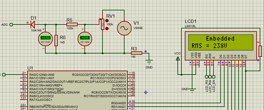 |
| 238V AC Measured |
 |
| 91V AC Measured |
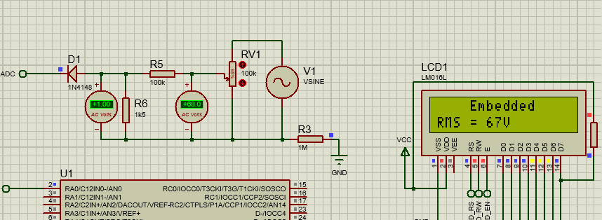 |
| 67V AC Measured |
Note: AC is very dangerous and the circuit shown here is just non-isolated circuit and can cause serious damage if not used properly, use it at your own risk.
The main file of the project is as follows:
The main file of the project is as follows:
/*
* File: main.c
* Author: Embedded Laboratory
*
* Created on November 10, 2016, 10:24 PM
*/
#include "config.h"
#include "lcd_16x2.h"
uint32_t led_timestamp = 0;
static uint8_t led_state = FALSE;
uint32_t adcUpdate_timestamp = 0;
char lcd_msg[LCD_BUFFER_LEN] = { 0 };
#define ADC_BUFFER_LENGTH 40u
uint16_t adc_data[ADC_BUFFER_LENGTH] = {0};
uint8_t adc_data_index = 0;
void main()
{
// Select 16MHz Internal Oscillator
OSCCONbits.IRCF = 0x07; // From 1MHz to 16MHz
InitTimer0 ();
LCD_Init ();
// Configure ADC
ANSELAbits.ANSA0 = 1; // Disable the Digital Input Buffer on AN0
TRISAbits.RA0 = 1; // AN0 as Input Pin
ADCON1bits.PVCFG = 0x00; // +Vref = AVDD
ADCON1bits.NVCFG = 0x00; // -Vref = AVSS
ADCON2bits.ADFM = 0x01; // Right Justified
ADCON2bits.ACQT = 0x01; // 2TAD
ADCON2bits.ADCS = 0x05; // FOSC/16
ADCON0bits.CHS = 0x00; // AN0 Selected
ADCON0bits.ADON = 1; // Enable ADC
sprintf (lcd_msg, " Embedded");
LCD_Print_Line (0, lcd_msg);
sprintf ( lcd_msg, "AC RMS = %dV", 0u);
LCD_Print_Line (1, lcd_msg);
LCD_Update ();
while(1)
{
// LCD Update Task
if( millis() - led_timestamp > 1000u )
{
led_timestamp = millis();
if( led_state )
{
led_state = FALSE;
sprintf (lcd_msg, " Laboratory");
}
else
{
led_state = TRUE;
sprintf (lcd_msg, " Embedded");
}
LCD_Print_Line (0, lcd_msg);
LCD_Update ();
}
// ADC Update Task
if( millis() - adcUpdate_timestamp >= 1u )
{
uint32_t ac_value = 0;
adcUpdate_timestamp = millis ();
ADCON0bits.CHS = 0x00; // AN0 Selected
ADCON0bits.GODONE = 1; // Start Conversion
while(ADCON0bits.GO == 1);
uint8_t adc_lo = ADRESL;
uint8_t adc_hi = ADRESH;
adc_data[adc_data_index] = (uint16_t)(adc_hi << 8) | (uint16_t)adc_lo;
adc_data_index++;
if( adc_data_index >= ADC_BUFFER_LENGTH )
{
adc_data_index = 0u;
// Time to Process and Display Data
uint32_t adc_filter_val = 0;
uint16_t adc_buf_local = 0;
for( uint8_t i=0; i<ADC_BUFFER_LENGTH; i++ )
{
adc_buf_local = adc_data[i];
adc_filter_val += ((uint32_t)(adc_buf_local*(uint32_t)adc_buf_local ));
}
// 625*625 = 390625
// 128*128 = 16384
// 625^2 / 128^2 = 23.8414
adc_filter_val = (uint32_t)((float)adc_filter_val * 23.84);
adc_filter_val /= ADC_BUFFER_LENGTH; // mean squared sum
adc_filter_val *= 2;
ac_value = (uint16_t)sqrt(adc_filter_val);// root mean square
ac_value *= 68u;
ac_value /= 1000u;
sprintf ( lcd_msg, "AC RMS = %luV", ac_value);
LCD_Print_Line (1, lcd_msg);
LCD_Update();
}
}
}
}


can explained 23.84 derivation?
ReplyDeleteYes Sure.
DeleteFormula for Vrms Calculation is Vrms = sqrt( (V1^2+V2^2+...+Vn^2)/n)
But the values we measure using Micro-controller are digital values.
So to convert Digital Value to Voltage, we have to use the following formula:
Voltage(mv) = ADC Count * 5000(mv)/1024
By Simplifying the above expression we get:
Voltage(mv) = ADC Count * 625/128
Now, in our Vrms formula, we have to put this value, but we can further simplify the formula by squaring and taking square root.
So instead of doing this.
Vrms = sqrt( ((625*ADC1/128)^2+(625*ADC2/128)^2+...+(625*ADCn/128)^2)/n)
We can do this.
Vrms = sqrt(625*625/(128*128) * sqrt((ADC1)^2+(ADC2)^2+...+(ADCn)^2)/n)
And Finally
Vrms = 23.84 * sqrt((ADC1)^2+(ADC2)^2+...+(ADCn)^2)/n)
I hope it is clear now, please reply here, if something is not clear.
Hi, Ian srirangappa. In ac voltmeter code as : adc_filter_val *= 2; here why you are multiplying by 2 ? Pl. Explain to me.
ReplyDeleteNegative half cycle is clipped using diode, so if we calculate the rms of this clipped signal, we will get half the value of real rms.
DeleteSo to compensate that, multiply by 2 is used.
Assuming that negative and positive cycle are exactly similar.
Hi sir. I am srirangappa is here. Code:#define USE_LCD_BUSY_FLAG is defined in lcd_16x2.h header file. But I'm not getting- updating of code in any of one of the files. Please Tell me sir where it is updating the FLAG. Thanking you.
ReplyDeleteIf busy flag macro is defined, then in software we are checking the busy bit to get the status of lcd controller.
DeleteYou can check lcd source file and see, the code is conditionally compiled.
If busy flag is set, lcd_busy function is used otherwise crude delay is used.
Note: delay will only work if free timer is running.
Hi, iam srirangappa here. in ac voltmeter code:#define USE_LCD_BUSY_FLAG is defined in hedder file lcd_16x2.h but iam not getting, where is the flag updating in any one of the file? Pl.explain about code:USE_LCD_BUSY_FLAG.
ReplyDeletePlease check my reply on above post.
DeleteIN4148 is this a zener diode? if it is a zener diode, will it works on this above circuit?
ReplyDeleteplease reply me sir...
No It's not a Zener Diode.
DeleteThe main purpose of this diode in this circuit is to clip the negative half cycle, as uC can't measure the negative signals.
thank you sir..
Deletesir, as per your circuit diagram, you connected phase or neutral with uC's ground through 1Mohm resistor. Is this not affect uC? and did you make this project on real time? (on hardware).. please reply me sir.... thanks in advance.....
ReplyDeleteThat was just required to run the simulation, in real circuit you can skip that and it will work properly.
DeleteBut make sure that this is a non isolated circuit.
HI, is this code written in mikroC pro please?
ReplyDeleteNo it's written for MPLAB XC8 compiler, but you can port it into mikroC easily.
DeleteHi Can I use the code with PIC16F877A?
ReplyDeleteYes you can use the same code with some modifications at driver level for adc.
DeleteHi, I installed MPLAB but even with MPLAB it didn't worked if you want I can send you the code and the errors please help me.
ReplyDeleteComplete code is available as download link, use that project.
DeleteKindly explain the calculation you have given in the code as:-
ReplyDelete625*625 = 390625
128*128 = 16384
625^2 / 128^2 = 23.8414
what does these values signifies?
help me in it please, i am designing the same project using atmega32.
Yes Sure
DeleteFormula for Vrms Calculation is Vrms = sqrt( (V1^2+V2^2+...+Vn^2)/n)
But the values we measure using Micro-controller are digital values.
So to convert Digital Value to Voltage, we have to use the following formula:
Voltage(mv) = ADC Count * 5000(mv)/1024
By Simplifying the above expression we get:
Voltage(mv) = ADC Count * 625/128
Now, in our Vrms formula, we have to put this value, but we can further simplify the formula by squaring and taking square root.
So instead of doing this.
Vrms = sqrt( ((625*ADC1/128)^2+(625*ADC2/128)^2+...+(625*ADCn/128)^2)/n)
We can do this.
Vrms = sqrt(625*625/(128*128) * sqrt((ADC1)^2+(ADC2)^2+...+(ADCn)^2)/n)
And Finally
Vrms = 23.84 * sqrt((ADC1)^2+(ADC2)^2+...+(ADCn)^2)/n)
I hope it is clear now, please reply here, if something is not clear.
sir i think,sqrt(625*625/(128*128) * sqrt((ADC1)^2+(ADC2)^2+...+(ADCn)^2)/n, would fetch 625/128 = 4.8828125, but your answer is 23.84 . Kindly explain it
Deletesir i think there is mathematical error in above,
DeleteVrms = sqrt(625*625/(128*128) * sqrt((ADC1)^2+(ADC2)^2+...+(ADCn)^2)/n), i think sqrt(625*625/(128*128) this would fetch 4.8828125.
kindly clear it.
Yes you are right.
DeleteBut the calculation is not incorrect.
Square root is taken after.
I used 23.84 and after taking square root it is 4.88
And you are directly taking that.
So both are correct.
Please check code, you will see.
I think there is some mathematical error in below text:-
ReplyDeleteVrms = sqrt( ((625*ADC1/128)^2+(625*ADC2/128)^2+...+(625*ADCn/128)^2)/n)
We can do this.
Vrms = sqrt(625*625/(128*128) * sqrt((ADC1)^2+(ADC2)^2+...+(ADCn)^2)/n)
And Finally
Vrms = 23.84 * sqrt((ADC1)^2+(ADC2)^2+...+(ADCn)^2)/n)
it should be 4.8828125 not 23.84 because sqrt of 625^2/128^2 will be 625/128=4.8828125
Yes you are right.
DeleteBut the calculation is not incorrect.
Square root is taken after.
I used 23.84 and after taking square root it is 4.88
And you are directly taking that.
So both are correct.
Please check code, you will see.
Sir I have done the same project with pic18f23k22 and I'm able to get the output.but actually I'm taking input to pic through current coil using opamp which will just act as buffer without any diode..now problem in facing is it is not varied according to answer rating..I mean to say like for 4 amp from coil I'm able to see 4.1 amps in serial terminal of pic..similarly for 6.1amp it is getting 17..for 10amps 38.2 like this.what might be the problem..?
ReplyDeletePlease share your circuit diagram then only i will be able to comment.
DeleteUse Contact Us Page to send me your schematic.
sorry for he late reply sir but still i have issue with this circuit.
DeleteCan you elaborate your problem
DeleteSir I have mailed you regarding the issue..can you please reply me back.
ReplyDeleteHi sorry for late reply.
DeleteAre you taking about that hand drawn image of circuit.
Can you please more elaborate that what you are trying to achieve with that.
Why you choosed thay circuit?
Did you run the simulation on this circuit?
What exactly problem you are facing?
Please provide detailed analysis with me over mail, then only i can think of something.
You can mail be, i will reply there.
sir i have sent you mail.Please revert me back.Thank you.
DeleteSir I have mailed you regarding the issue..can you please reply me back.
ReplyDeleteHi, can we have this code in MikroC please. and with MPLAB IDE does not include ADC.H please help me. the compiler shows the below msg:
ReplyDeleteconfig.c:8: error: (141) can't open include file "adc.h": No such file or directory
main.c:9: error: (141) can't open include file "adc.h": No such file or directory
I am so sorry, i just checked the download link and found that adc header and source files are not there.
DeleteI am really sorry for the inconvenience caused due to this.
I will update it really soon in 24hours.
Hey Sorry for the problem.
DeleteJust remove the line
#include "adc.h" from your code as it is not required because the ADC drivers are written directly in main.c file.
Please update me, if you are facing any other issue.
This issue is also corrected in blog post.
Did the same but now it is showing that
DeleteCLEAN SUCCESSFUL (total time: 104ms)
make: *** No rule to make target 'adc.h', needed by 'build/default/production/main.p1'. Stop.
BUILD FAILED (exit value 2, total time: 151ms)
I think that functions related to ADC are available only in adc.h header file. please provide that header file asap.
If you see the code, you will see that there is no adc functions, everything is written inside main file.
DeleteDid you removed the adc.h include from the program??
Please download the updated version, in this i have corrected this issue.
Please let me know if you are still facing the issue, i will recheck everything again.
yes I removed the #include adc.h from the code and also tried updated download link. still the problem exist. What should I do?
DeleteSorry for the problem, I can understand it is really frustrating.
DeleteMy bad i didn't give my 100% while updating the code.
Now coming to the solution.
You need to remove the adc.h from the config.c file also. After this you will be able to build this project.
Links are also updated.
PS: Initially I thought that I will create a library and will share it with users, and at a later stage I realized that, for this simple project this library is not required and I unfortunately I forget to remove the links of that from the project.
Now i removed these things completely, it should work fine.
Please update me if anyone faces any issue.
Sir, please provide adc.h file. Please update the download link asap.
ReplyDeleteSir now the problem is solved. the code is working without any error. Thanks for the updation.
ReplyDeleteWelcome :-)
DeleteSir can you make this code suit for 16f877a ? Please
Deletemy email id is sreens295@gmail.com
Please try yourself, it will be a simple task.
DeleteIn case of any problem contact us.
You can also use Contact Us page to contact me
Ok Sir please tell me what i have to change in the configuration to make the code suitable for 16f877a
DeleteThank you now it's working very well, can we request you for the same AC voltage meter circuit for Arduino please?
ReplyDeletePorting something from Arduino to any other micro, is little bit difficult task, but working on Arduino is very simple task, please try yourself.
DeleteIn case of any problem contact us.
You can also use Contact Us page to contact me
Well explained. Please help me out. My schematic does not use resistors in stepping down the 230 volt to 12 volt. I used transformer to first step down to 17volts, then use the bridge rectifier to convert AC to pulsating DC and finally, the capacitors and regulators to drive the pulsing DC to pure 5dc. Please, my problem is, since i am not using resistors how can I get 67.67 which is the total resistors value that scaled down the 230 volt to 5 volt. Also, how can I use MickroC Pro to write this code.Thanks
ReplyDelete230V is 5V at your micro adc pin.
ReplyDelete115 is how much at your micro adc pin????
Is it not possible to multiply the voltage measured at micro pin with 46 to get the exact voltage supplied?
In such situations i used to do take new input points and measure the output value.
For example
x = 230V then what is y
x = 100V then what is y
x = 50V then what is y
Similary take 5-10 more points and plot that data in Excel and determine the slope and intercept.
Using the line equation:
Y = mx + c
And use this to calculate your input adc voltage.
when reference voltage is not fix 5v but some time its a 4.94 and some time 4.84 so how we solve this problem?
ReplyDeleteAs you can see in the above circuit, Resistor R5 and R6 are used to drop down the AC voltage.
ReplyDeleteScaled Down Peak Voltage = Vpeak * (R6) / (R6+R7)
Peak Voltage for PIC, Vp,uc = 340 * 1.5/(101.5)
Vp, uc = 340 / 66.67
Vp, uc = 5.0246V
above the step can explain how the 66.67 will came ????
Hi sir, in the ac voltmeter, in voltage divider ckt.if taken output from diode to adc, in display shows non zero value even no voltage voltage energies. Please. Explain it.
ReplyDeleteHi, if i have sine wave with a vpp of 2V @100hz it's possible to use your code and circuit ?
ReplyDeleteHello sir pls why are u using 40u. What does that 'u' stands for, cant we just use 40?
ReplyDeleteHow did you calculate for the adc count values in the table
ReplyDeleteCan we use same code for CCS complier iam wanna simulate in proteus
ReplyDeleteYou need to modify the syntax, logic remains same.
DeleteHello Sir can you please explain if DC shifted waveform is used for same project
ReplyDeleteWhat is the role of 1 Meg resistor in the circuit? Will the resistor not affect the ADC value as it is in series with the voltage sensing resistors?
ReplyDeletegood explanation
ReplyDeleteSir, Why you use these two lines, kindly replay back
ReplyDeleteac_value *= 68u;
ac_value /= 1000u;
The AC Voltage is scaled down by using voltage divider circuit, and to compensate for that, we need to multiply back the scaling factor, which is 101.5/1.5 = 67.67 rounded off to 68.
DeleteI hope this is clear now.