Tuesday, December 20, 2022

Weather Monitoring Using ESP32 and InfluxDB

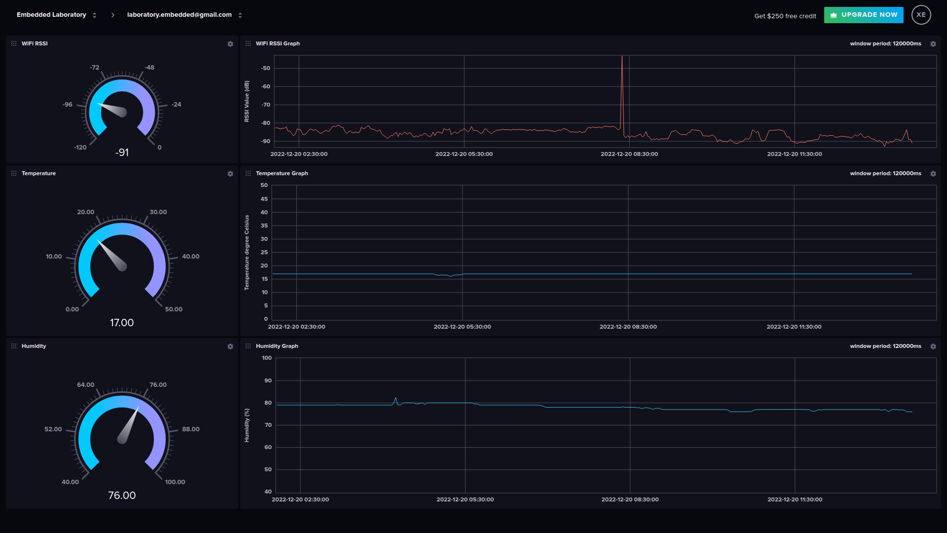
In this post, I will demonstrate how we can use the ESP32 module to sense the temperature and humidity from the DHT11 sensor and send this data to the InfluxDB cloud database, and then using InfluxDB and Grafana Dashboard, we can visualize this data in the form of graphs and gauges. Below is the image of the dashboard created in InfluxDB.

Note: Grafana Dashboard post will be a separate topic else this will be a very long post.

Dashboard in InfluxDB Cloud
You can watch the video or read the below post.

Prerequisite for this Tutorial

Note: I prefer PlatformIO with VSCode for my software development, but the same project will work on the Arduino platform also. In PlatformIO you have to click on Libraries and then search for the library and then add that library to the project, while in Arduino you have to use "Library Manager" and search for the library and install it. Both are really simple methods and I assume you all are very much familiar with them.

As a first step, we will use the ESP32 to capture the temperature and humidity information from the DHT11 temperature sensor. Fortunately, the software library is already available for this purpose from Adafruit.

Install the DHT sensor library if using PlatformIO or Arduino as shown in the image below.

Install Adafruit DHT Sensor Library for PlatformIO

Install Adafruit DHT Sensor Library for Arduino


Install the InfluxDB library if using PlatformIO or Arduino as shown in the image, this library has the name ESP8266 but don't worry about that, it works very well with ESP32 also.

Install InfluxDB ESP8266 Library for PlatformIO

Install InfluxDB ESP8266 Library for Arduino

DHT11 Sensor Interfacing

As a first step, we will test the DHT11 sensor to make sure it is working, this is basically a modular approach that helps the software development easier.
Let's start our coding, first, we need to include the DHT sensor include files in the project as shown below.
#include <DHT.h>
#include <DHT_U.h>
 
The next step is to select the DHT sensor type and the pin it is connected to, here it is connected to ESP32 pin 12, we have also created a macro "DHT11_REFRESH_TIME", this macro is used to trigger the measurement from the DHT11 sensor, this we will see below.
#define DHTPIN (12)
#define DHTTYPE (DHT11)

#define DHT11_REFRESH_TIME (5000u)
 
The next step is to create the DHT sensor object and define some variables to store temperature and humidity data, another variable is created named "dht_refresh_timestamp", this variable along with macro "DHT11_REFRESH_TIME" is used to get the temperature and humidity after every 5 seconds, which is programmed in "DHT11_REFRESH_TIME" macro.
static uint8_t dht11_temperature = 0;
static uint8_t dht11_humidity = 0u;
DHT dht(DHTPIN, DHTTYPE);
 
Below are the two main important functions, one is the "DHT11_TaskInit" function and another is the "DHT11_TaskMng()" function.

DHT11_TaskInit

This function is called inside the "setup" function and it basically setup the sensor pins and sets pull timings, also initializes the "dht_refresh_timestamp" variable with the current values millisecond value using "millis()" function.

DHT11_TaskMng

This function is called inside the "loop" function and it basically triggers the temperature and humidity measurements and prints the information on the serial port and also saves the data into the variables "dht11_temperature" and "dht11_humidity".
The content of both of these functions are as below.
static void DHT11_TaskInit( void )
{
dht.begin();
// delay(2000);
dht_refresh_timestamp = millis();
}
 
static void DHT11_TaskMng( void )
{
uint32_t now = millis();
float temperature, humidity;
if( now - dht_refresh_timestamp >= DHT11_REFRESH_TIME )
{
dht_refresh_timestamp = now;
// Reading temperature or humidity takes about 250 milliseconds!
// Sensor readings may also be up to 2 seconds 'old' (its a very slow sensor)
humidity = dht.readHumidity();
// Read temperature as Celsius (the default)
temperature = dht.readTemperature();
// Check if any reads failed and exit early (to try again).
if (isnan(humidity) || isnan(temperature) )
{
Serial.println(F("Failed to read from DHT sensor!"));
}
else
{
Serial.print(F("Humidity: "));
Serial.print(humidity);
Serial.print(F("% Temperature: "));
Serial.print(temperature);
Serial.println(F("°C "));
// store this in the global variables
dht11_humidity = (uint8_t)humidity;
dht11_temperature = (uint8_t)temperature;
}
}
}
 
void setup()
{
System_Init();
DHT11_TaskInit();
}

void loop()
{
DHT11_TaskMng();
}
 

We will test this much and if this works we will proceed further with the connection to the InfluxDB cloud server.

Creating InfluxDB Database

With the above piece of code, we can get the temperature and humidity data from the DHT11 sensor, and as a next step we have to store this data on the InfluxDB database we need an account for that, which can be created for free of cost for primary usage.
To create a free account, register with an email id on this link. And once you are registered you have the possibility to select from the following three options.
  • AWS Amazon Web Services
  • Google Cloud
  • Microsoft Azure
You can select anyone of them, and opt for "Free Account", which looks like this.
InfluxDB Plan Type

InfluxDB Database Connection Details

InfluxDB has already done some work for us in interfacing Arduino-based devices, so we can take advantage of it, this is shown below where we get the option of "Client Libraries", one can click on "Arduino" icon and follow along.
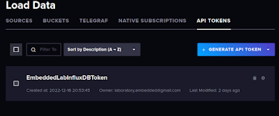
But let's do it differently here, although it means the same thing, we need two things here, one is "Bucket" and the other thing is "API Tokens" by which the other application can access the InfluxDB database.
 
Click on Generate API Token button to generate token.
Generate API Token

Click on Create Bucket button to create a bucket. The purpose of bucket is to collect all data
Create Bucket

And now next step is to update our program to connect with the InfluxDB server and send data to the InfluxDB database. And for this we will include the InfluxDB-related header files and also the WiFiMulti header file which will handle all WiFi-related operations for the ESP32 chip, so now our header file inclusion will look like this.
 
#include <Arduino.h>
#include <WiFiMulti.h>
#include <InfluxDbClient.h>
#include <InfluxDbCloud.h>
#include <DHT.h>
#include <DHT_U.h>
 

The next step is to fill in the WiFi Router's SSID and Password information so that our ESP32 module can be connected to the router and the internet.
 
#define WIFI_SSID "Enter SSID Here"
#define WIFI_PASSWORD "Enter Password Here"
 

After this, we must enter the InfluxDB database-related information, as mentioned below.
 
#define INFLUXDB_URL "????????????"
#define INFLUXDB_TOKEN "????????????"
#define INFLUXDB_ORG "????????????"
#define INFLUXDB_BUCKET "????????????"
 
 
All of this information we can get from the InfluxDB account, like for example we just created the "Bucket" and also generated the "API Token", so that information needs to be entered here, similarly URL and also the organization, which is just your email id.
 
The next step is to set the time zone and this is done using the following statements.
Here I have specified the Central European Time i.e. CET.
 
// Set timezone string according to https://www.gnu.org/software/libc/manual/html_node/TZ-Variable.html
// Examples:
// Pacific Time: "PST8PDT"
// Eastern: "EST5EDT"
// Japanesse: "JST-9"
// Central Europe: "CET-1CEST,M3.5.0,M10.5.0/3"
#define TZ_INFO "CET-1CEST,M3.5.0,M10.5.0/3"
 
 
Once this is done we need to define the Device Name, and also a macro named "INFLUXDB_SEND_TIME" to send data periodically to InfluxDB database.
#define DEVICE "ESP32"
#define INFLUXDB_SEND_TIME (10000u)
 
After this, I will create a WiFi object, a Point object which stores the data for the bucket, and an InfluxDB client object for connecting and sending data to the InfluxDB database, and this can be done using the following line of code.
 
// InfluxDB client instance with preconfigured InfluxCloud Certificate
InfluxDBClient client(INFLUXDB_URL, INFLUXDB_ORG, INFLUXDB_BUCKET, INFLUXDB_TOKEN, InfluxDbCloud2CACert);

// Data point
Point sensor("Sensor_Data");

WiFiMulti wifiMulti;
 
 
Now let's start working on writing our important function, just like we did for the DHT11 sensor, this part also includes three important functions, first "WiFi_Setup", the second one is "InfluxDB_TaskInit()" and the last and most important one "InfluxDB_TaskMng()"

WiFi_Setup

This function connects the ESP32 with the WiFi router and connects it to the internet, here first configure the ESP32 in station mode and then connect it to the router, as shown below.
 
static void WiFi_Setup( void )
{
// Connect WiFi
Serial.println("Connecting to WiFi");
WiFi.mode(WIFI_STA);
wifiMulti.addAP(WIFI_SSID, WIFI_PASSWORD);
while (wifiMulti.run() != WL_CONNECTED)
{
Serial.print(".");
delay(500);
}
Serial.println();
}
 

InfluxDB_TaskInit

This function synchronizes time and connects with the InfluxDB database as shown with the help of the below piece of code, we also added a "Tag" named device, to identify that this data is coming from this device which in this case is "ESP32"
 
static void InfluxDB_TaskInit( void )
{
// Add constant tags - only once
sensor.addTag("device", DEVICE);

// Accurate time is necessary for certificate validation & writing in batches
// For the fastest time sync find NTP servers in your area:
// https://www.pool.ntp.org/zone/
// Syncing progress and the time will be printed to Serial.
timeSync(TZ_INFO, "pool.ntp.org", "time.nis.gov");

// Check server connection
if (client.validateConnection())
{
Serial.print("Connected to InfluxDB: ");
Serial.println(client.getServerUrl());
}
else
{
Serial.print("InfluxDB connection failed: ");
Serial.println(client.getLastErrorMessage());
}
}
 

InfluxDB_TaskMng

This function is the most important function and this function, and this function sends the WiFi RSSI value of the WiFi, with Temperature and Humidity data to the InfluxDb database. As shown in the below piece of source code.
This function executes every 10 seconds, but I would suggest it changed to every minute as temperature and humidity values don't change that quickly.
In this function, the following things are done.
  • Clear All Fields for the Point
  • Then add fields, one is RSSI, then DHT11 Temperature, and then DHT11 Humidity
  • Once the above step is done we send this to Serial for debugging purposes to see if everything looks fine or not.
  • The next step is that check if the WiFi is still connected or not.
  • If connected we will write the Point data to the InfluxDB server
 
static void InfluxDB_TaskMng( void )
{
uint32_t now = millis();
if( now - influxdb_send_timestamp >= INFLUXDB_SEND_TIME )
{
influxdb_send_timestamp = now;
sensor.clearFields();
// Report RSSI of currently connected network
sensor.addField( "rssi", WiFi.RSSI() );
// add temperature and humidity values also
sensor.addField( "temperature", dht11_temperature );
sensor.addField( "humidity", dht11_humidity );
// Print what are we exactly writing
Serial.print("Writing: ");
Serial.println(client.pointToLineProtocol(sensor));
// If no Wifi signal, try to reconnect it
if (wifiMulti.run() != WL_CONNECTED)
{
Serial.println("Wifi connection lost");
}
// Write point
if (!client.writePoint(sensor))
{
Serial.print("InfluxDB write failed: ");
Serial.println(client.getLastErrorMessage());
}
}
}
 
 
Download the code from the GitHub Repository
 
Or you can use the below-mentioned code also.
/**
* Basic Write Example code for InfluxDBClient library for Arduino
* Data can be immediately seen in a InfluxDB UI: wifi_status measurement
* Enter WiFi and InfluxDB parameters below
*
* Measures signal level of the actually connected WiFi network
* This example supports only InfluxDB running from unsecure (http://...)
* For secure (https://...) or Influx Cloud 2 use SecureWrite example
**/

#include <Arduino.h>
#include <WiFiMulti.h>
#include <InfluxDbClient.h>
#include <InfluxDbCloud.h>
#include <DHT.h>
#include <DHT_U.h>

// Project Macros
#define WIFI_SSID "Enter SSID Here"
#define WIFI_PASSWORD "Enter Password Here"
#define INFLUXDB_URL "????????????"
#define INFLUXDB_TOKEN "????????????"
#define INFLUXDB_ORG "????????????"
#define INFLUXDB_BUCKET "????????????"

// Set timezone string according to https://www.gnu.org/software/libc/manual/html_node/TZ-Variable.html
// Examples:
// Pacific Time: "PST8PDT"
// Eastern: "EST5EDT"
// Japanesse: "JST-9"
// Central Europe: "CET-1CEST,M3.5.0,M10.5.0/3"
#define TZ_INFO "CET-1CEST,M3.5.0,M10.5.0/3"

#define DEVICE "ESP32"

// DHT Sensor Configuration Macros
#define DHTPIN (12)
#define DHTTYPE (DHT11)

#define DHT11_REFRESH_TIME (5000u)
#define INFLUXDB_SEND_TIME (10000u)

// Priavate Variables

// InfluxDB client instance with preconfigured InfluxCloud Certificate
InfluxDBClient client(INFLUXDB_URL, INFLUXDB_ORG, INFLUXDB_BUCKET, INFLUXDB_TOKEN, InfluxDbCloud2CACert);

// Data point
Point sensor("Sensor_Data");

WiFiMulti wifiMulti;

static uint8_t dht11_temperature = 0;
static uint8_t dht11_humidity = 0u;
DHT dht(DHTPIN, DHTTYPE);

// Task Time related Variables
static uint32_t dht_refresh_timestamp = 0u;
static uint32_t influxdb_send_timestamp = 0u;

// Private Function Prototypes
static void System_Init( void );
static void WiFi_Setup( void );
static void DHT11_TaskInit( void );
static void DHT11_TaskMng( void );
static void InfluxDB_TaskInit( void );
static void InfluxDB_TaskMng( void );

void setup()
{
System_Init();
WiFi_Setup();
DHT11_TaskInit();
InfluxDB_TaskInit();
}

void loop()
{
DHT11_TaskMng();
InfluxDB_TaskMng();
}

// Private Function Definitions
static void System_Init( void )
{
Serial.begin( 115200 );
// TODO: XS
}

static void WiFi_Setup( void )
{
// Connect WiFi
Serial.println("Connecting to WiFi");
WiFi.mode(WIFI_STA);
wifiMulti.addAP(WIFI_SSID, WIFI_PASSWORD);
while (wifiMulti.run() != WL_CONNECTED)
{
Serial.print(".");
delay(500);
}
Serial.println();
}

static void DHT11_TaskInit( void )
{
dht.begin();
// delay(2000);
dht_refresh_timestamp = millis();
}

static void DHT11_TaskMng( void )
{
uint32_t now = millis();
float temperature, humidity;
if( now - dht_refresh_timestamp >= DHT11_REFRESH_TIME )
{
dht_refresh_timestamp = now;
// Reading temperature or humidity takes about 250 milliseconds!
// Sensor readings may also be up to 2 seconds 'old' (its a very slow sensor)
humidity = dht.readHumidity();
// Read temperature as Celsius (the default)
temperature = dht.readTemperature();
// Check if any reads failed and exit early (to try again).
if (isnan(humidity) || isnan(temperature) )
{
Serial.println(F("Failed to read from DHT sensor!"));
}
else
{
Serial.print(F("Humidity: "));
Serial.print(humidity);
Serial.print(F("% Temperature: "));
Serial.print(temperature);
Serial.println(F("°C "));
// store this in the global variables
dht11_humidity = (uint8_t)humidity;
dht11_temperature = (uint8_t)temperature;
}
}
}

static void InfluxDB_TaskInit( void )
{
// Add constant tags - only once
sensor.addTag("device", DEVICE);

// Accurate time is necessary for certificate validation & writing in batches
// For the fastest time sync find NTP servers in your area:
// https://www.pool.ntp.org/zone/
// Syncing progress and the time will be printed to Serial.
timeSync(TZ_INFO, "pool.ntp.org", "time.nis.gov");

// Check server connection
if (client.validateConnection())
{
Serial.print("Connected to InfluxDB: ");
Serial.println(client.getServerUrl());
}
else
{
Serial.print("InfluxDB connection failed: ");
Serial.println(client.getLastErrorMessage());
}
}

static void InfluxDB_TaskMng( void )
{
uint32_t now = millis();
if( now - influxdb_send_timestamp >= INFLUXDB_SEND_TIME )
{
influxdb_send_timestamp = now;
// Store measured value into point
sensor.clearFields();
// Report RSSI of currently connected network
sensor.addField( "rssi", WiFi.RSSI() );
// add temperature and humidity values also
sensor.addField( "temperature", dht11_temperature );
sensor.addField( "humidity", dht11_humidity );
// Print what are we exactly writing
Serial.print("Writing: ");
Serial.println(client.pointToLineProtocol(sensor));
// If no Wifi signal, try to reconnect it
if (wifiMulti.run() != WL_CONNECTED)
{
Serial.println("Wifi connection lost");
}
// Write point
if (!client.writePoint(sensor))
{
Serial.print("InfluxDB write failed: ");
Serial.println(client.getLastErrorMessage());
}
}
}


Visualizing Data on InfluxDB Database

Now the data is sent to the InfluxDB database, it is very easy to visualize the data, we just have to go to following the following steps as mentioned in the image.
Creating Dashboard Using Data Explorer

  1. Select the Data Explorer menu available on the left-hand side.
  2. Select the Bucket, which in this case is "HomeBucket"
  3. The next step is to select the measurement, which in this case is "Sensor_Data"
  4. The next step is to select the "fields" either RSSI, Humidity, or Temperature, we can select each field individually also, and place them on the Dashboard.
  5. The next step is to select the "device" which in our case is "ESP32"
  6. The next step is to select the data duration, here I have specified that I wanted to view the past 12 hours of data.
  7. The next step is to select the "Aggregate Function" here I selected "last"
  8. The next step is to click on the "Submit" button, this will generate a graph.
  9. And if you like this graph, you can click on the "Save As Graph" button, if you want to play with some other types of graphs, then you can play around with the "Customize" button and "Graph" drop-down menu to see various options.
I hope you like this post of mine, in case you have any queries or questions feel free to contact me using the comments section.
I will also update the links to the video tutorial and the link to the next related post, which displays the dashboard using Grafana.

No comments:

Post a Comment