In the last post, I showed you guys how to use OLED Display based on SSD1306 controller with the Microchip PIC micro-controller, and in this post, I will use the OLED libraries from that post and make temperature and humidity display system.
For measuring temperature and humidity I am going to use DHT11 sensor, this is a cheap sensor and can be found very easily in the local market or on online stores.
Introduction

The following diagram shows the duration of the bit-0 and bit-1 pulses.
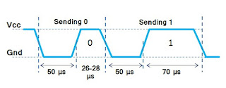 So the complete timing diagram can be represented using the image below.
 Using micro-controller we have to first simulate the pulses and then decode the pulses from the DHT11 sensor.
Components Required:
The Software is written in mikroC for PIC and can be ported easily to any other micro-controller, and is as follow:
Understanding Software:
The software is basically divided into two modules, one is getting data from DHT11 sensor and another is displaying data on OLED display. Let's see these two things separately.
Getting Data from DHT11 Sensor
At the start of the program, the initialization function is called, this function will configure the timer module, but will not start it.
Whenever you have to measure the temperature and humidity data, just call the following function.
This function will first send the start signal and then check the DHT11 response and after that, this function will update the internal buffer with temperature and humidity value, which can be later used using the following two functions.
It's is advised to first check the error value, like I did in the code, if you are receiving an error, then the values received from the above functions will not be the correct values, and we can discard them as I did in the above program.
Updating Temperature and Humidity Values on OLED Display
As a first step, temperature and humidity values are converted into characters and are stored in a array, and after using the OLED library function, these values are displayed on the OLED as text.
This is for temperature only, the same method is used for humidity value also.
Now in the next step, I will show you how to draw a bar diagram based on the current temperature and humidity values.
The idea is very simple, we just need to use the two library functions, one is for drawing rectangle and another is for drawing filled rectangle.
The blank rectangle will always remain constant, and using the software and the current temperature and humidity values, the size of the fill rectangle will be controlled as done below.
As you can see above, first we have drawn a rectangle and then based on the current temperature value, percentage is calculated and size of Fill Rectangle is determined and then it is drawn.
Finally we need to call the update function to update everything on the OLED display.
The same method is used for updating the humidity, and by using this approach we will get a very cool looking display on OLED, which will vary with changes in temperature. This can be seen in the video above.
Download Completed Source Code with Simulation file by Clicking Here.
Read the following post also.
For measuring temperature and humidity I am going to use DHT11 sensor, this is a cheap sensor and can be found very easily in the local market or on online stores.
 |
| Setup |
DHT11 sensor is a 4-pin device and it operates from 3.5 to 5.5V power supply.
| Pin Name | Description |
|---|---|
| 1st Pin | VCC (3.3V-5.5V) |
| 2nd Pin | Data Pin |
| 3rd Pin | Not Connected |
| 4th Pin | Ground |
DHT11 can measure temperature from 0-50 °C with an accuracy of ±2°C and relative humidity ranging from 20-95% with an accuracy of ±5%.
This sensor has it's own proprietary 1-wire protocol, so there are no modules inside micro-controller for this protocol, that's why the protocol needs to be implemented in software.
The following timing diagrams describe the data transfer protocol between a micro-controller and the DHT11 sensor.
The micro-controller first sends the "Start" signal, and then DHT11 sensor responds with a response signal, as shown below.

Start Signal: Micro-controller will pull-low the data line for 25ms and after that high for 30usec, and after issuing this signal, micro-controller should make the data line as input and wait for the response from the DHT11 sensor.
Response: DHT11 sensor will pull-low the data line for 80usec and then pull-high the data line for another 80usec, and after this DHT11 sensor will send the temperature and humidity information in the form of pulse.
Data Response: After sending the response DHT11 sensor will provide the Humidity Data, Temperature Data and Checksum in the forum of digital pulses. In total it will send 40 pulses which is equivalent to 40-bit which means 5 bytes.
The following table describe the information content of each byte.
The following table describe the information content of each byte.
| Data Byte | Description |
|---|---|
| 1st Byte | Relative Humidity Integer Value |
| 2nd Byte | Relative Humidity Decimal Value |
| 3rd Byte | Temperature Integer Value |
| 4th Byte | Temperature Decimal Value |
| 5th Byte | Checksum Byte for Verification |
The following diagram shows the duration of the bit-0 and bit-1 pulses.


Components Required:
The connection diagram is shown below, you just have to connect the OLED display with I2C pins of PIC and DHT11 sensor can be connected with any micro-controller pin, which can act as input and output pin.
 |
| Connection Diagram |
Have a look at this video, to see how the complete system works.
The Software is written in mikroC for PIC and can be ported easily to any other micro-controller, and is as follow:
#include "DHT11.h"
#include "OLED_I2C.h"
#include <stdint.h>

#define MIN_TEMPERATURE     0
#define MAX_TEMPERATURE     50
#define MIN_HUMIDITY        0
#define MAX_HUMIDITY        100

// DHT11 Sensor Image, to be displayed on OLED
const code char DHT11_Image[512] =
{
  0,   0,   0, 248, 136, 200, 168, 168, 168, 168, 152, 152, 248, 152, 152, 152, 248, 152, 152, 152, 248, 152, 152, 152, 248, 152, 152, 152, 248, 152, 152, 152, 152, 248, 152, 152, 152, 248,   0,   0,   0,   0,   0,   0,   0,   0,   0,   0,   0,   0,   0,   0,   0,   0,   0,   0,   0,   0,   0,   0,   0,   0,   0,   0,   0,   0,   0,   0,   0,   0,   0,   0,   0,   0,   0,   0,   0,   0,   0,   0,   0,   0,   0,   0,   0,   0,   0,   0,   0,   0,   0,   0,   0,   0,   0,   0,   0,   0,   0,   0,   0,   0,   0,   0,   0,   0,   0,   0,   0,   0,   0,   0,   0,   0,   0,   0,   0,   0,   0,   0,   0,   0,   0,   0,   0,   0,   0,   0,
  0,   0,   0, 255, 255,  68,  68,  68,  68,  68,  68,  68, 255,  68,  68,  68, 255,  68,  68,  68, 255,  68,  68,  68, 255,  68,  68,  68, 255,  68,  68,  68,  68, 255,  68,  68,  68, 255,  68,  68,  68,  68,  68,  68,  68,  68,  68,  68,  68,  68,  68,  68,  68,  68,  68,   0,   0,   0,   0,   0, 255, 255, 255,   3,   3,   3,   7,  14, 254, 252, 248,   0,   0, 255, 255, 255,  96,  96,  96,  96, 255, 255, 255,   0,   0,   3,   3,   3,   3, 255, 255, 255,   3,   3,   3,   3,   6,   6,   2, 255, 255, 255,   0,   0,   0,   0,   0,   6,   6,   2, 255, 255, 255,   0,   0,   0,   0,   0,   0,   0,   0,   0,   0,   0,   0,   0,   0,   0,
  0,   0,   0, 255, 127, 164, 164,  36,  36,  36,  36,  36, 255,  36,  36,  36, 255,  36,  36,  36, 255,  36,  36,  36, 255,  36,  36,  36, 255,  36,  36,  36,  36, 255,  36,  36,  36, 255,  36,  36,  36,  36,  36,  36,  36,  36,  36,  36,  36,  36,  36,  36,  36,  36,  36,   0,   0,   0,   0,   0,  31,  31,  31,  24,  24,  24,  28,  14,  15,   7,   1,   0,   0,  31,  31,  31,   0,   0,   0,   0,  31,  31,  31,   0,   0,   0,   0,   0,   0,  31,  31,  31,   0,   0,   0,   0,  24,  24,  24,  31,  31,  31,  24,  24,  24,   0,   0,  24,  24,  24,  31,  31,  31,  24,  24,  24,   0,   0,   0,   0,   0,   0,   0,   0,   0,   0,   0,   0,
  0,   0,   0,   7,   4,   4,   4,   5,   5,   5,   6,   6,   7,   6,   6,   6,   7,   6,   6,   6,   7,   6,   6,   6,   7,   6,   6,   6,   7,   6,   6,   6,   6,   7,   6,   6,   6,   7,   0,   0,   0,   0,   0,   0,   0,   0,   0,   0,   0,   0,   0,   0,   0,   0,   0,   0,   0,   0,   0,   0,   0,   0,   0,   0,   0,   0,   0,   0,   0,   0,   0,   0,   0,   0,   0,   0,   0,   0,   0,   0,   0,   0,   0,   0,   0,   0,   0,   0,   0,   0,   0,   0,   0,   0,   0,   0,   0,   0,   0,   0,   0,   0,   0,   0,   0,   0,   0,   0,   0,   0,   0,   0,   0,   0,   0,   0,   0,   0,   0,   0,   0,   0,   0,   0,   0,   0,   0,   0
};

void interrupt() iv 0x0008
{
  if( TMR1IF_bit )
  {
    dht11_int_handler();
  }
}

void main()
{
  uint8_t error;
  uint8_t temperature_text[5], temperature;
  uint8_t humidity_text[5], humidity;
  UART1_Init(9600);
  OLED_Init();
  dht11_init();
  OLED_ClearDisplay();
  OLED_Image( DHT11_Image );
  OLED_Update();
  // Give Sufficient time to display the image
  Delay_ms(2000);
  while(1)
  {
    error = dht11_start_measurement();
    if( error == DHT11_NO_ERROR )
    {
      uint16_t percentage;
      uint16_t x, y;
      // If this is not used, then you will not see changes in bar
      OLED_ClearDisplay();
      // Get Temperature Data
      temperature = dht11_temperature();
      temperature_text[0] = temperature/10 + 48;
      temperature_text[1] = temperature%10 + 48;
      temperature_text[2] = ' ';
      temperature_text[3] = 'C';
      temperature_text[4] = 0;  // Null Character
      // Draw Rectangle
      x = OLED_Width()-(8*4);
      OLED_Rectangle( 0, 0, x, 7, WHITE );
      percentage = temperature * 100;
      percentage = percentage/(MAX_TEMPERATURE - MIN_TEMPERATURE );
      x = percentage * x /100;
      OLED_FillRectangle( 0, 0, x, 7, WHITE );
      OLED_Write_Text( OLED_Width()-(8*3), 0, temperature_text );
      // Get Humidity Data
      humidity = dht11_humidity();
      humidity_text[0] = humidity/10 + 48;
      humidity_text[1] = humidity%10 + 48;
      humidity_text[2] = ' ';
      humidity_text[3] = '%';
      humidity_text[4] = 0;   // Null Character
      x = OLED_Width()-(8*4);
      OLED_Rectangle( 0, 15, x, 23, WHITE );
      percentage = humidity * 100;
      percentage = percentage/(MAX_HUMIDITY - MIN_HUMIDITY );
      x = percentage * x /100;
      OLED_FillRectangle( 0, 15, x, 23, WHITE );
      OLED_Write_Text( OLED_Width()-(8*3), 15, humidity_text );

      OLED_Write_Text( 0, 25, "Sensor Ok");
      OLED_Update();
      /*
      Uncomment the code below, to view values on UART
      UART1_Write( dht11_temperature()/10 + 48 );
      UART1_Write( dht11_temperature()%10 + 48 );
      UART1_Write(',');
      UART1_Write( dht11_humidity()/10 + 48 );
      UART1_Write( dht11_humidity()%10 + 48 );
      UART1_Write_Text("\r\n");
      */
    }
    else
    {
      UART1_Write_Text("DHT11 Not Connected");
      switch(error)
      {
        case DHT11_NO_RESPONSE:
          OLED_Write_Text( 0, 25,"Sensor: No Response");
          break;
        case DHT11_CHECKSUM_ERROR:
          OLED_Write_Text( 0, 25,"Sensor: Checksum Error");
          break;
        default:
          OLED_Write_Text( 0, 25,"Sensor: Unknown Error");
          break;
      };
      OLED_Update();
    }
    Delay_ms(1000);
  }
}
Understanding Software:
The software is basically divided into two modules, one is getting data from DHT11 sensor and another is displaying data on OLED display. Let's see these two things separately.
Getting Data from DHT11 Sensor
At the start of the program, the initialization function is called, this function will configure the timer module, but will not start it.
dht11_init();
Whenever you have to measure the temperature and humidity data, just call the following function.
error = dht11_start_measurement();
This function will first send the start signal and then check the DHT11 response and after that, this function will update the internal buffer with temperature and humidity value, which can be later used using the following two functions.
temperature = dht11_temperature();
humidity = dht11_humidity();
It's is advised to first check the error value, like I did in the code, if you are receiving an error, then the values received from the above functions will not be the correct values, and we can discard them as I did in the above program.
Updating Temperature and Humidity Values on OLED Display
As a first step, temperature and humidity values are converted into characters and are stored in a array, and after using the OLED library function, these values are displayed on the OLED as text.
// Get Temperature Data
temperature = dht11_temperature();
temperature_text[0] = temperature/10 + 48;
temperature_text[1] = temperature%10 + 48;
temperature_text[2] = ' ';
temperature_text[3] = 'C';
temperature_text[4] = 0;  // Null Character
OLED_Write_Text( OLED_Width()-(8*3), 0, temperature_text );
This is for temperature only, the same method is used for humidity value also.
Now in the next step, I will show you how to draw a bar diagram based on the current temperature and humidity values.
The idea is very simple, we just need to use the two library functions, one is for drawing rectangle and another is for drawing filled rectangle.
The blank rectangle will always remain constant, and using the software and the current temperature and humidity values, the size of the fill rectangle will be controlled as done below.
// Draw Rectangle
x = OLED_Width()-(8*4);
OLED_Rectangle( 0, 0, x, 7, WHITE );
percentage = temperature * 100;
percentage = percentage/(MAX_TEMPERATURE - MIN_TEMPERATURE );
x = percentage * x /100;
OLED_FillRectangle( 0, 0, x, 7, WHITE );
As you can see above, first we have drawn a rectangle and then based on the current temperature value, percentage is calculated and size of Fill Rectangle is determined and then it is drawn.
Finally we need to call the update function to update everything on the OLED display.
OLED_Update();
The same method is used for updating the humidity, and by using this approach we will get a very cool looking display on OLED, which will vary with changes in temperature. This can be seen in the video above.
 |
| DHT11 Data on OLED Display |
Read the following post also.


Hi the simulation file you have made is in protues 8.7 and I have 8.6 therefore I can't open the simulation file. please help me.
ReplyDeleteHi
DeleteSorry don't have the older version of proteus with me.
The schematic is very simple and i think you can draw it easily.
Thank you so much..................
DeleteAlso do you have pure sine wave code and circuit please?
DeleteWelcome.
DeleteSorry I don't have sine wave code.