The use of a graphical LCD (GLCD) drastically changes the look of your project. It provides more freedom for presenting data than HD44870-based character LCDs. Today we will see how to interface a KS0108 (name of the display controller chip) based GLCD to a PIC microcontroller. In this tutorial, we will focus on exploring the built-in GLCD Library of mikroC Pro for the PIC compiler to display more complex texts and objects. Since GLCDs are real resource-hungry devices (in terms of required I/O pins and memory), a bigger size PIC microcontroller (PIC18F4550) is selected for this experiment.
Theory The graphical LCD used in this experiment is based on the KS0108B controller, which is a 128×64 pixel monochromatic display. The KS0108B is a dot matrix LCD segment driver with 64-channel output. On the other hand, the KS0107B is a 64-channel common driver which generates the timing signal to control the two KS0108B segment drivers. The KS0108B and KS0107B are very popular controllers and have made their way into many graphical LCDs. The internal block diagram of the GLCD module is shown below.
GLCD Block Diagram
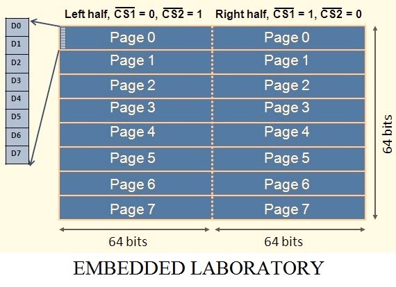
The GLCD has a total of 8 pages, starting from page 0 to Page 7, as shown below:
Please refer to your GLCD Datasheet for the connection Diagram, or follow our circuit diagram.
The KS0107/KS0108 does not have a character generator so this must be implemented in the micro-controller firmware. The LCD controller supports a handful of instructions which are summarized in the table shown below. Note that the RS (D/I) pin is high only during data read and data write operations, and stays low when a transmitted byte is an instruction.
GLCD Commands
The schematic diagram which this tutorial uses is as follow:
Schematic Diagram
The code is written in the mikroC compiler and uses the compiler's in-built library, to download the code click here.
The program Output is shown below:
First Screen
Second Screen
NOTE: As this tutorial is based on PIC18F4550 and PORTB is also used, so please make sure that Analog To Digital Converter is disabled in the Configuration Setting of PIC18F4550, otherwise the program will compile without error, but nothing will appear on Graphical Lcd.
Mikroelektronika MikroC has a wonderful tool to convert Monochrome Bitmap images into code, so you can use your monochrome Bitmap images to generate code for displaying images, have a look at the following video, to get more information on this.
I have the same project which you have download so even if i send it again it will be the same files. Can you show me how you are opening the project. Just share the steps how you are opening the project.
I have the same project which you have download so even if i send it again it will be the same files. Can you show me how you are opening the project. Just share the steps how you are opening the project.
Ghafoor Samadi, What you wanted to know is how to add the C file to the project in mikroc. What you need to do is create a new project in mikroc and copy and paste the C code into the project and compile to generate the file. HEX needed to pic both proteus and real pic with pic kit 3 recorder for example. Research how to create a new project in Mikroc. Hugs.
 Please refer to your GLCD Datasheet for the connection Diagram, or follow our circuit diagram.


hi how can I transfer the c file to MikroC please?
ReplyDeleteSorry I didn't get the meaning of transferring the c file to mikroC.
DeleteThis project is already written in mikroC.
But it's not opening in MikroC this why I'm asking how to open the file in MikroC please.
DeleteIt looks strange.
DeleteCan you share the snapshot of the problem on my email id.
matlab.academy@gmail.com
Sorry Dear, is it possible to send me the complete project please as I'm new with the system please? e-mail address is (ghafoor.samadi786@gmail.com)
DeleteI have the same project which you have download so even if i send it again it will be the same files.
DeleteCan you show me how you are opening the project.
Just share the steps how you are opening the project.
I have the same project which you have download so even if i send it again it will be the same files.
DeleteCan you show me how you are opening the project.
Just share the steps how you are opening the project.
Ghafoor Samadi, What you wanted to know is how to add the C file to the project in mikroc. What you need to do is create a new project in mikroc and copy and paste the C code into the project and compile to generate the file. HEX needed to pic both proteus and real pic with pic kit 3 recorder for example. Research how to create a new project in Mikroc. Hugs.
ReplyDelete